This is a RC controller TX & RX unit with nRF24L01+
nRF24L01+ / with PA and LNA for longer range

facts:
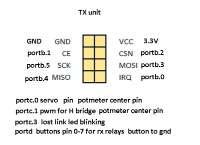
TX
1 x potmeter for servo
1 x potmeter for pwm H bridge
8 buttons for rx output
RX
1 x servo
2 output for H bridge pwm
8 output for relays ect
Setup 2.4Ghz channel 100 at 256Kbit speed 5 bytes


H bridge used at this link :
https://www.eeweb.com/project/circuit_projects/pwm-dc-motor-controller-using-mosfets-and-ir2110-h-bridge-driver
http://www.circuit-projects.com/fp/motor-driver/schematic.jpg
Files : internal 8Mhz clock is used
schematic
Atmega8 hex/bin
Atmega48 hex/bin
Atmega88 hex/bin
nRF24L01+ / with PA and LNA for longer range
facts:
TX
1 x potmeter for servo
1 x potmeter for pwm H bridge
8 buttons for rx output
RX
1 x servo
2 output for H bridge pwm
8 output for relays ect
Setup 2.4Ghz channel 100 at 256Kbit speed 5 bytes
H bridge used at this link :
https://www.eeweb.com/project/circuit_projects/pwm-dc-motor-controller-using-mosfets-and-ir2110-h-bridge-driver
http://www.circuit-projects.com/fp/motor-driver/schematic.jpg
Files : internal 8Mhz clock is used
schematic
Atmega8 hex/bin
Atmega48 hex/bin
Atmega88 hex/bin